When it comes to powering industrial machinery and large-scale equipment, understanding 3 phase motor are the workhorses of the electrical world. They are efficient, reliable, and capable of handling heavy loads. However, wiring a understanding 3 phase motor can be a daunting task for those who are not familiar with electrical systems. In this guide, we will walk you through the process of understanding and creating a understanding 3-phase motor wiring diagram, step by step.
What is a Three-Phase Motor?
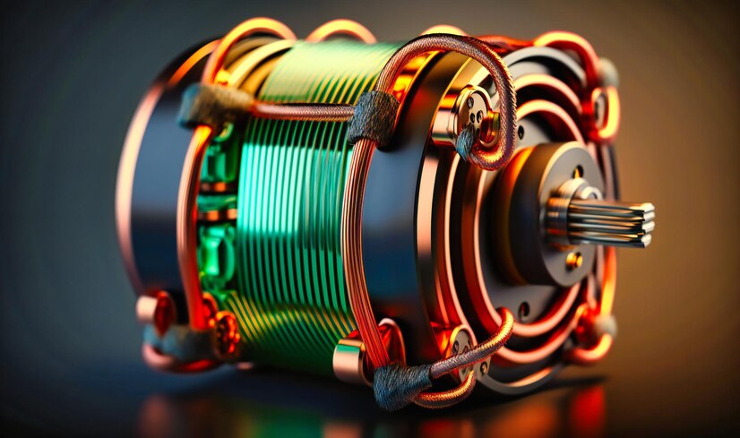
Before we delve into the wiring diagram, let’s start with the basics. A three-phase motor is a type of electric motor that operates on three alternating currents. These motors are commonly used in industrial and commercial applications due to their robust performance and efficiency.
Benefits of Three-Phase Motors
- High Efficiency: Three-phase motors are known for their energy efficiency, making them cost-effective to operate over the long term.
- Constant Power: They provide a steady and continuous power supply, ideal for applications that require constant torque and speed.
- Reliability: Three-phase motors are durable and less prone to overheating compared to single-phase motors.
- High Starting Torque: These motors can handle heavy starting loads without compromising their performance.
Now that we understand the advantages of three-phase motors, let’s move on to the wiring diagram.

Components Needed
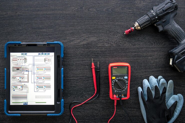
Before you start creating a 3-phase motor wiring diagram, gather the following components and tools:
- Three-phase motor
- Motor starter
- Circuit breaker
- Contactor
- Overload relay
- Control circuit devices (e.g., switches, push buttons)
- Wiring cables
- pliers, wire strippers, screwdrivers, and other standard electrical tools
Step-by-Step Guide to Wiring a 3-Phase Motor
1. Safety First
Always prioritize safety when working with electrical systems. Make sure the power supply is locked out and off to avoid any unintentional starts. Put on the proper personal protective equipment (PPE), such as safety glasses and gloves.
2. Identify Motor Leads
Find out what voltage the motor runs on and how it is wired. Most three-phase motors have six leads, which can be connected in either a star (Y) or delta (Δ) configuration, depending on the application and voltage supply.
3. Motor Starter Wiring
Connect the motor to the motor starter. The starter typically consists of a contactor and an overload relay. Ensure that the connections match the manufacturer’s specifications and that the overload relay is appropriately sized for the motor.
4. Control Circuit Wiring
Create the control circuit for your motor. This includes wiring push buttons, switches, and other control devices to the control terminals on the contactor. The motor can be safely started and stopped thanks to this circuit.
5. Power Supply Wiring
Connect the three-phase power supply to the motor starter through a circuit breaker. Make sure the wiring is correctly sized to handle the motor’s current requirements and that it complies with local electrical codes.
6. Test the System
After completing the wiring, double-check all connections for accuracy. Then, slowly power up the system and test the motor’s operation. Ensure that it starts, stops, and runs smoothly without any issues.
7. Troubleshooting
If you encounter any problems during testing, refer to the motor and starter manufacturer’s documentation for troubleshooting guidance. Common issues may include incorrect wiring, overload settings, or faulty components. visit us for more information


